Arizona and Pacific Railroad Construction Articles
Featuring
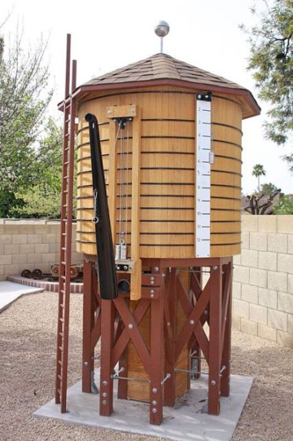
The Water Tank
Arizona and Pacific Railroad Water Tank Construction

Outside of laying rail, the construction of the water tank was our first big project on the Arizona & Pacific Railroad. We started on the water tank project in the fall of 2003. Dave and I had never built a water tank and didn’t have access to any drawings or plans so we learned about water tank construction as we went along.
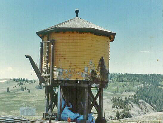
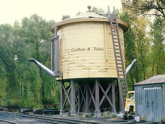
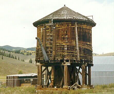
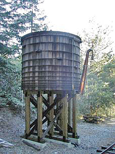
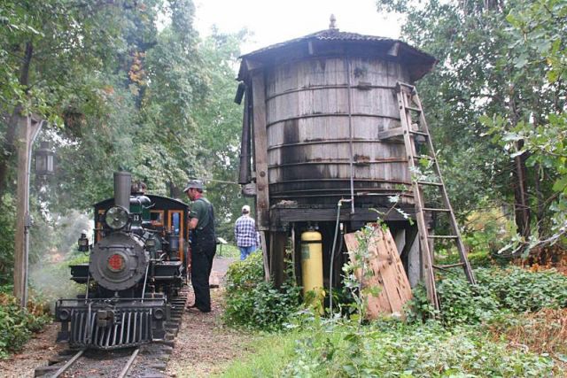
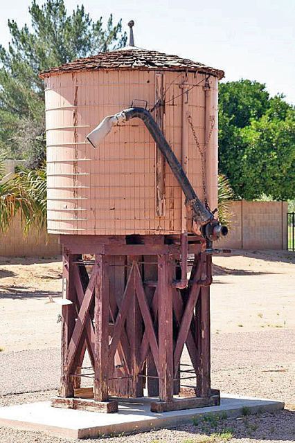
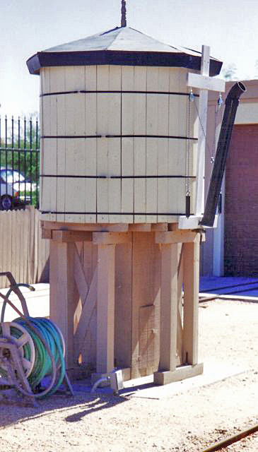
We spent a few weeks researching photo archives for photographs of Colorado narrow gauge railroad water tanks for examples of features that we liked and wanted to incorporate into our tank design. We also took numerous photographs and measurements of the tanks at the Redwood Valley Railroad in Tilden Park, California, the Hillcrest and Wahtoke in Reedley, CA, the Desert Breeze Railroad in Chandler, AZ and the Stillman-McCormick Railroad Park in Scottsdale, AZ. We also carefully examined photographs of several full size prototypes. Of particular interest was the DRGW tank in Osier, Colorado which is now part of the Cumbres and Toltec Scenic Railroad.
|
|
|
Early on, there was one thing that we knew for certain – we really liked the 5/12 scale narrow gauge dimensions of the water tanks on the Redwood Valley, Hillcrest and Wahtoke and Stillman-McCormick Railroad. At 16 inch gauge, our railroad is technically not 5/12 narrow gauge, but we like that look and size and have adopted it for our construction on the A & P.
|
|
|
|
There are common characteristics among the water tanks we liked in terms of frame and cross bracing of the support legs, but there are also as many variations as similarities. We started working our way through the design process. We also decided that to look prototypical Colorado narrow gauge, we would need a frost box in the center of the cross bracing.
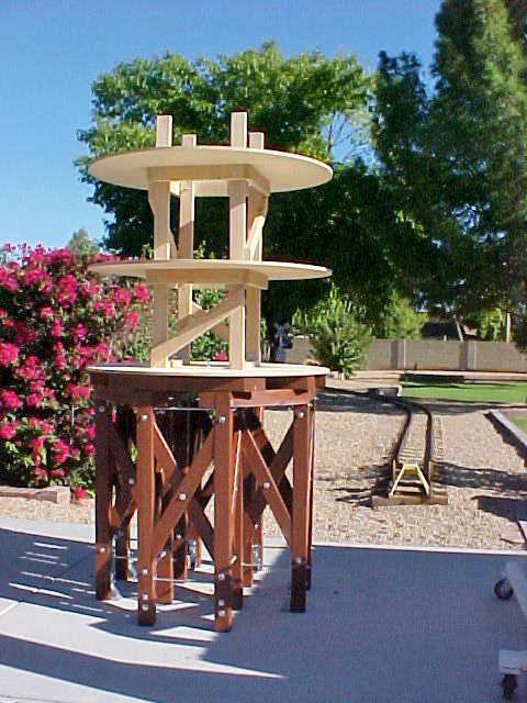
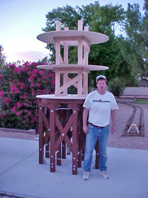
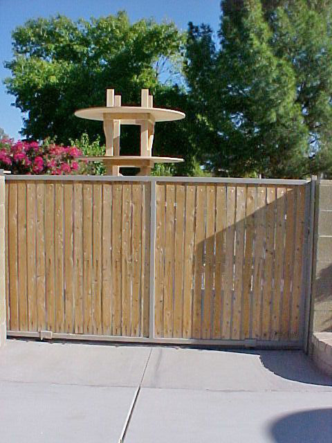
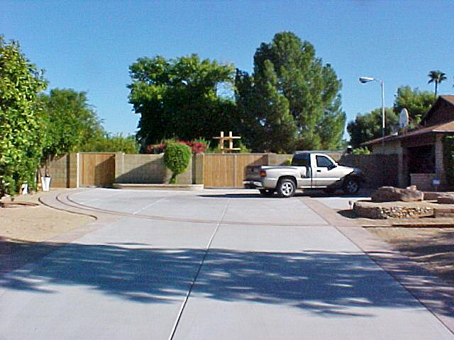
Dave built a scale-model of the support legs and bracing in his garage and it was very helpful in working out most of the engineering challenges before we started on our trackside version. Construction on the 5/12 tank started in early 2004 as we built the frame and cross-bracing on a concrete pad just behind my backyard gate. Once we added the support structure for the tank portion of the structure, it extended above my 6 foot tall block wall and I’m sure some of the neighbors were thinking I had lost it…
|
|
|
|
We poured and finished the concrete pad next to the rail where we wanted the tank to stand. Note: we should have done this earlier and assembled the frame and cross bracing on that site as it was brutally heavy and getting it back there was not an easy task…
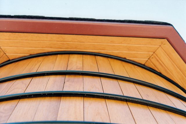
We played with our math and cut some examples and determined that we needed a 1 degree bevel on the barrel slats for the best fit. The slats are hickory as are the eaves. The custom barrel rings are steel and powder coated in black. They were rolled to the proper dimension in the shop of one of our friends and although their design is a little different than the prototype, they look good and serve the same purpose.
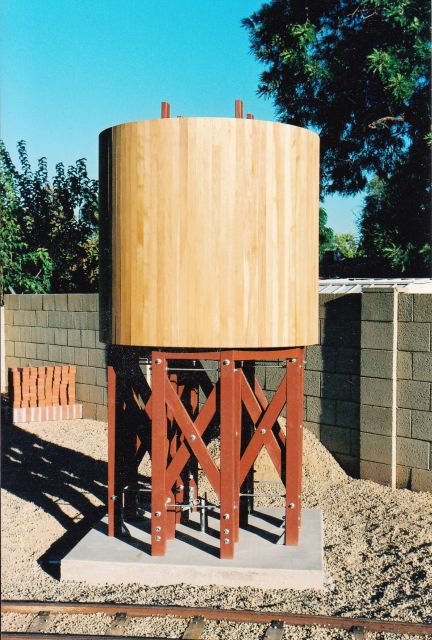
|
We spent a great deal of time on the project in 2004 and made a great deal of progress as the plumbing, the water level gauge, ladder and first version of the counter balance for the spout were completed and installed.
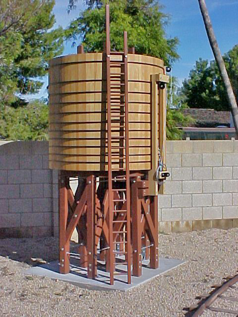
|
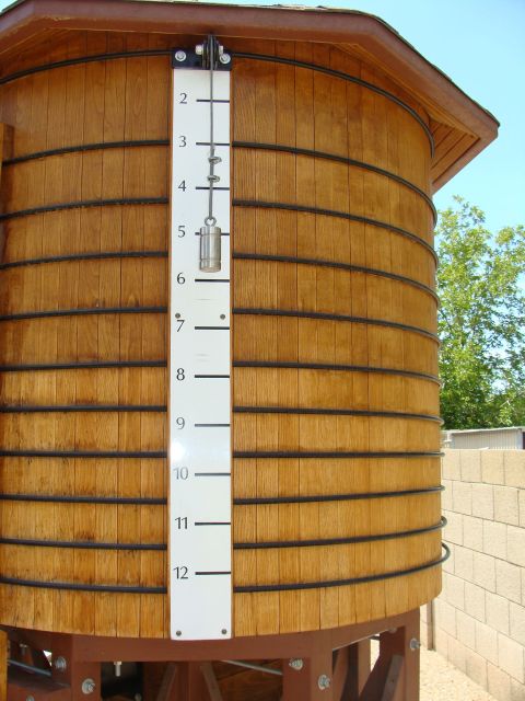
|
At the end of the year, several major components including the roof, the spout and the frost box were still under construction.
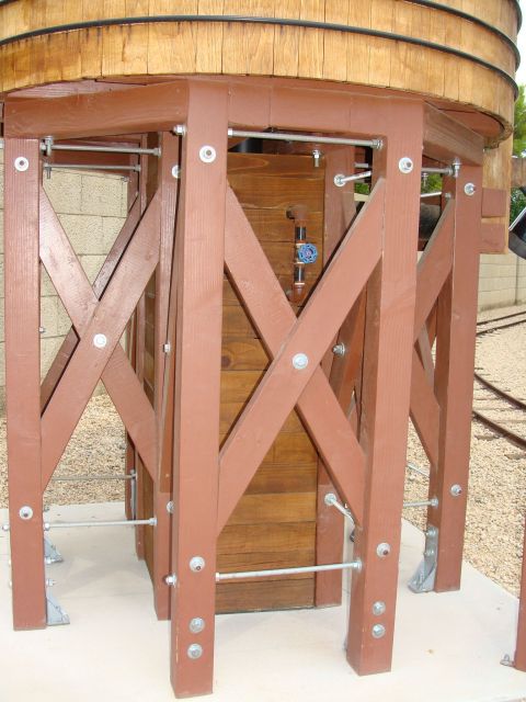
|
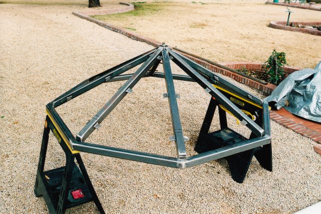
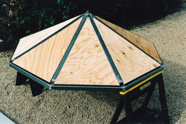
There were two basic roof designs on the prototypical water tanks – round and octagonal. We decided on the octagonal roof as we thought it had more character and made for a more interesting structure. We ran into some engineering and structural challenges when we started construction of the roof. With so many short pieces of wood toe-nailed together at the center, it just didn’t have the strength I wanted. We ended up fabricating the roof out of steel with plywood panel inserts for the roof and hickory inserts for the eaves. To state that it is very solid is an understatement.
|
|
|
For several weeks after the structural components of the roof were complete, it stood without paper or shingles as I made the final decision on the color and type of shingles I wanted to use and finalized the interior. The plywood roof panels were removable and still allowed access to the interior – I was thinner then…
|
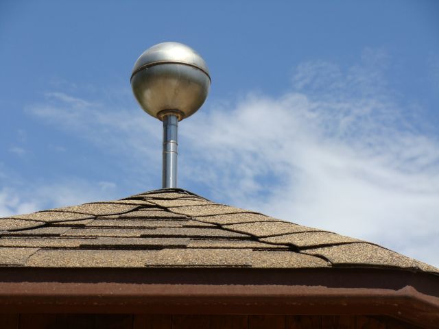
The top finial was another interesting design element. We saw several different varieties, but the D & RG had a few tanks with the round ball on top and we opted for that treatment. Dave found the perfect sized finial in a scrap yard and we machined a post to mount it to the steel portion of the roof.
|

|
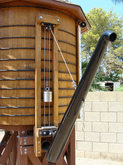
The spout counterweight created a challenge in getting the weight just right so that the spout will stay in any position on its own. The slide rods for the counterweight that prevent it from clanking into the tank on the way up and down was another interesting project as was the spout itself, but we worked our way through those challenges.
|
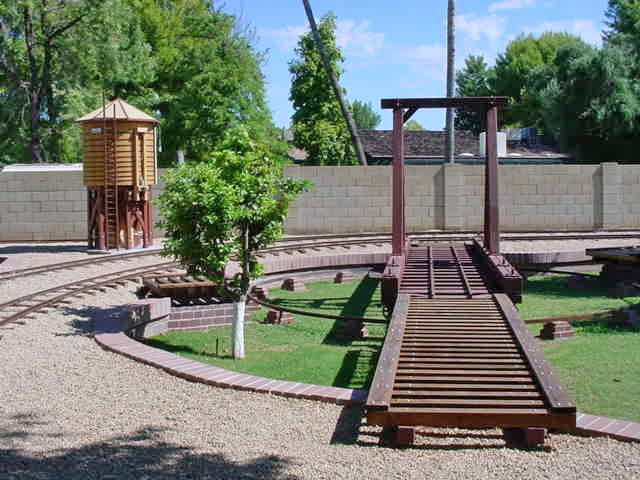
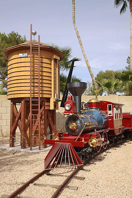
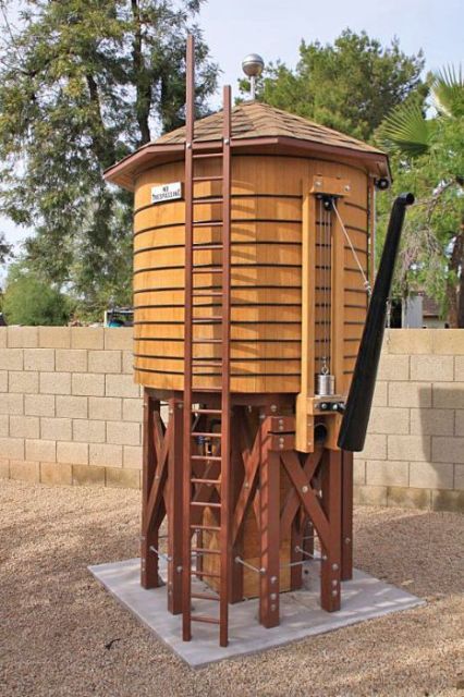
In November 2005, we completed our fully functional water tank which is 61 inches in diameter and 12 feet tall. The octagonal roof created some interesting engineering and construction challenges which we overcame. The octagonal roof is covered with dimensional shingles. The spout counter weight, guide rods and bottom plate are all stainless steel as are the water depth gauge weight and the lightning rod. The spout is several pieces of steel pipe cut, welded and ground to our dimensions; it is smooth as glass and looks like one piece of metal. The ladder is a working ladder. It took us close to two and a half years to take this project from research and design to the fully complete this project.
|
|